![]()
![]()
![]()
![]()
![]()
![]()
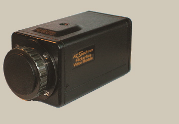
Flickerfree Color Video Assist
A video assist (video tap) is an accessory for a motion picture camera that provides a video feed from the camera lens. It is used to allow the director or operator to see on a video monitor or computer screen what is in the camera's frame without having to look through the viewfinder, as well as allowing video to be captured that can be used to create an immediate rough cut, if needed. If the motion picture camera runs at a frame per second rate (e.g. 24 fps) different from the video frame rate, NTSC: 29.97 fps, PAL: 25 fps, then the monitor image will flicker. The flickerfree video assist is designed to produce a 100% flickerfree monitor image for camera speeds ranging from 10 to 150 fps. A Sony CCD (Charge Coupled Device) solid stage EXview HAD (Hole Accumulated Diode) image sensor provides it with high resolution, high sensitivity and outstanding color fidelity. The computerized video assist electronics allows the image to be electronically flipped horizontally and/or vertically, which is useful when operating the unit with various video optics systems (different cameras, e.g. Arriflex or Aaton). This video assist can be supplied from a 12V or 24V battery (autoranging) and is equipped with a noise filter which provides a clear monitor image even if the camera motor is noisy. The low power consumption, only 220mA/12V or 130mA/24V, gives your camera battery a longer life.
Specifications:
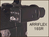
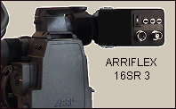
This
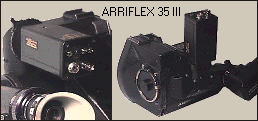
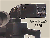
flickerfree video assist can be easily mounted to Arriflex
cameras.
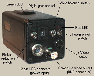
Gain
control set by decimal switch:
"0" - Manual Gain (MG) 0dB
"1" - MG 2dB
"2" - MG 4dB
"3" - MG 6dB
"4" - MG 8dB
"5" - MG 10dB
"6" - MG 12dB
"7" - MG 14dB
"8" - Auto Gain Control (AGC) is ON
"9" - FR/A mode, 0dB
The
flicker reduction switch (3 position):
- When set to the lower position, flickerfree mode FF is
activated and the green LED is lit. This mode is designed to
produce a flickerfree image for camera speeds ranging from 10 to
150 fps.
- When set to the middle position, flicker reduction is off and
the green LED is not lit. The video assist is in normal mode.
NTSC - When set to the upper position, flickerfree mode FF30 is
activated and the green LED is lit. This mode provides a 100%
flickerfree image when operating at a camera speed of 29.97 fps
or 30 fps. In this mode, flickering is reduced by 70% for camera
speeds other than 29.97 fps and 30 fps.
PAL - When set to the upper position, flickerfree mode FF24/25 is
activated and the green LED is lit. This mode provides a 100%
flickerfree image when operating at a camera speed of 24 fps or
25 fps.
If the video
assist is powered from the camera's accessory connector,
flickerfree modes FF , FF30 (NTSC) and FF24/25 (PAL) will only be
active when the camera is running. Once the camera is stopped,
normal mode will resume. If the digital gain control is set to
"9", flickerfree FR/A mode will be active even when the
camera is stopped. If the video assist is supplied from the 12V
battery using a cable with a 4 pin XLR connector, activation of
the flickerfree FR/A mode will not depend on whether the camera
is running.
White balance switch (3 position):
- Upper: Auto White Balance is ON. The white balance is adjusted
according to the color temperature transition of the subject.
This mode is suitable for shooting with variable lighting.
- Middle: 3200K (fixed) - for indoor shooting under incandescent
light.
- Lower: 5600K (fixed) - for outdoor shooting on sunny days.
Power on/off switch (2 position):
- Upper: the video assist is ON and the red LED is lit
- Lower: power is OFF and the red LED is not lit
The accessory connector which is installed on
the side of the video assist is designed to supply power 12V DC,
600mA to LCD monitor.
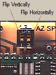 DIP switches located on the
electronics board: By using the DIP switches located on
the electronics board you can flip the image horizontally
(mirroring) or vertically (upside down).
DIP switches located on the
electronics board: By using the DIP switches located on
the electronics board you can flip the image horizontally
(mirroring) or vertically (upside down).
Input
/Output 12 pin HRS connector (pin configuration):
Pin 1 - OV, GND
Pin 2 - Input +24V or +12V
Pin 3 - Y- GND
Pin 4 - Y output of S-video
Pin 5 - NC
Pin 6 - Input : /ERUN, F ist
Pin 7 - NC
Pin 8 - C output of S-video
Pin 9 - C- GND
Pin 10 - NC
Pin 11 - input : if +12V connected then FR/A mode is active
Pin 12 - NC
![]() - Flicker Test of the unit on YouTube
- Flicker Test of the unit on YouTube
| HOME | SERVICE | E-MAIL | PAYMENT OPTIONS | WARRANTY |